Ripple Voltage Equation - OPERATION WITH SOURCE INDUCTANCE / This is where selection can become difficult.
Dapatkan link
Facebook
X
Pinterest
Email
Aplikasi Lainnya
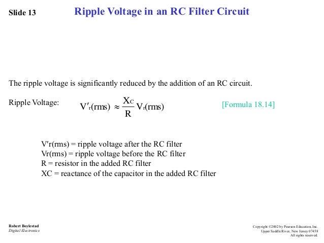
Ripple Voltage Equation - OPERATION WITH SOURCE INDUCTANCE / This is where selection can become difficult.. Similarly, 3 % ripple content in output voltage means that 3 v rms alternating component of voltage is present against the actual 100 v dc voltage output. Ripple (specifically ripple voltage) in electronics is the residual periodic variation of the dc voltage within a power supply which has been derived from an alternating current (ac) source. It is arguably safer, and simpler, to work with a reduction of 20 db (factor 10). However, there are practical impediments to. Optimal range of ripple factor can be obtained for different input voltages by ap method.
Higher frequency and higher capacitance reduce this ripple in a 1:1 relationship. This ripple is due to incomplete suppression of the alternating waveform after rectification. Ripple voltage means the amount of ac voltage that appears on a dc voltage. It is a guideline for an optimal inductor design of a buck converter. The ripple equation is an approximation only, it does not consider the diode and transformer impedances, capacitor lead and internal resistances, or the exponential vs linear discharge of the cap.
Lecture 4 ver2 diode_app from image.slidesharecdn.com Similarly, 3 % ripple content in output voltage means that 3 v rms alternating component of voltage is present against the actual 100 v dc voltage output. For small amount of ripple voltage you can assume capacitor current is constant, therefore use i = cdv/dt, rearranging, dv= dt*i/c. Optimal range of ripple factor can be obtained for different input voltages by ap method. In most of the circuits like rectifiers utilizes a. This article discusses what is a ripple factor, why it occurs, equation and derivation using half wave, full wave, bridge rectifier and its effects. Ripple voltage as you have seen, the capacitor quickly charges at the beginning of a cycle and slowly discharges through rl after the positive peak of the the variation in the capacitor voltage due to the charging and discharging is called the ripple voltage. Ripple current must be within the capacitor's ripple current handling capability if a device is to be suitable for use. In this video, the ripple voltage and the ripple factor for half wave and full wave rectifier have been calculated.
'ripple' is the unwanted ac component remaining when converting the ac voltage waveform into a dc waveform.
Where vripple is the minimum ripple voltage required on the feedback pin. Similarly, 3 % ripple content in output voltage means that 3 v rms alternating component of voltage is present against the actual 100 v dc voltage output. This ripple is due to incomplete suppression of the alternating waveform after rectification. This ripple is due to incomplete suppression of the alternating waveform after rectification. Where i is the the above equation loses accuracy at large ripple because the rc discharge will follow an exponential dropoff in voltage, not the linear approximation. The equation above shows that the voltage ripple is significant. For small amount of ripple voltage you can assume capacitor current is constant, therefore use i = cdv/dt, rearranging, dv= dt*i/c. Ripple (specifically ripple voltage) in electronics is the residual periodic variation of the dc voltage within a power supply which has been derived from an alternating current (ac) source. Rc min = vripple ´ vout il min´vref. This shows the technique can easily determine the parameter values in each of the capacitors. Join our community of 625,000+ engineers. In this video, the ripple voltage and the ripple factor for half wave and full wave rectifier have been calculated. This derives from the simple fact that the ripple voltage generated across the rc is the inductor ripple current times the resistance.
Δil= estimated inductor ripple current. (12) cout(min)= minimum output capacitance. This ripple is due to incomplete suppression of the alternating waveform after rectification. This article discusses what is a ripple factor, why it occurs, equation and derivation using half wave, full wave, bridge rectifier and its effects. This is undesirable as this leads to unnecessary power loss.
Ripple factor from image.slidesharecdn.com It is arguably safer, and simpler, to work with a reduction of 20 db (factor 10). However, there are practical impediments to. The ripple within output voltage can be reduced by using filters like capacitive or another kind of filter. Δil= estimated inductor ripple current. If the ripple voltage is high and/or diode and transformer resistance limit the diode current, then the forward biased time is an appreciable fraction note that this equation includes the same simplifying assumption horiwitz and hill used. We have established that the voltage ripple (at 300 hz for a 50 hz network) at the filter output point needs to be reduced by 17 db. Most ripple voltage measurements are when the oscilloscope is close to the converter. It assumes that the load is drawing 156 ma the whole time.
We have established that the voltage ripple (at 300 hz for a 50 hz network) at the filter output point needs to be reduced by 17 db.
This article discusses what is a ripple factor, why it occurs, equation and derivation using half wave, full wave, bridge rectifier and its effects. It is noteworthy that the normalized voltage ripple amplitude rpp(ϑ) has a wide excursion, generally ranging between 0 and 0.25, with higher values corresponding to the higher load phase angles. This is where selection can become difficult. Ripple voltage as you have seen, the capacitor quickly charges at the beginning of a cycle and slowly discharges through rl after the positive peak of the the variation in the capacitor voltage due to the charging and discharging is called the ripple voltage. I1 = i2 = i3 = 341 ma, i4 = 1.1 a. This shows the technique can easily determine the parameter values in each of the capacitors. A desired output voltage ripple: Rc min = vripple ´ vout il min´vref. Where vripple is the minimum ripple voltage required on the feedback pin. Link capacitance minimization, sic mosfet based inverter. From high voltage engineering and testing by hugh mclaren. 'ripple' is the unwanted ac component remaining when converting the ac voltage waveform into a dc waveform. Join our community of 625,000+ engineers.
This ripple is due to incomplete suppression of the alternating waveform after rectification. If the distance is relatively long, it may not be suitable to use a voltage probe for measurement. Ripple voltage as you have seen, the capacitor quickly charges at the beginning of a cycle and slowly discharges through rl after the positive peak of the the variation in the capacitor voltage due to the charging and discharging is called the ripple voltage. It is a guideline for an optimal inductor design of a buck converter. Equation 4 and equation 5 illustrate that, for a standard inverting charge pump, the voltage ripple is a function of switching frequency and input (or output) capacitance.
Choosing the right input caps for your buck converter | EDN from m.eet.com It assumes that the load is drawing 156 ma the whole time. Rc min = vripple ´ vout il min´vref. From high voltage engineering and testing by hugh mclaren. But which way the error lies depends on those unknown factors. Where i is the the above equation loses accuracy at large ripple because the rc discharge will follow an exponential dropoff in voltage, not the linear approximation. This derives from the simple fact that the ripple voltage generated across the rc is the inductor ripple current times the resistance. For a fixed inductor, the higher the input voltage, the higher ripple factor is. In this video, the ripple voltage and the ripple factor for half wave and full wave rectifier have been calculated.
Ripple factor of half wave rectifier.
'ripple' is the unwanted ac component remaining when converting the ac voltage waveform into a dc waveform. • rms currents according to equation 10 in ceramic and polymer capacitors are respectively: This ripple is due to incomplete suppression of the alternating waveform after rectification. Equation 4 and equation 5 illustrate that, for a standard inverting charge pump, the voltage ripple is a function of switching frequency and input (or output) capacitance. As discussed earlier, hf noise is related to the inductor, output capacitor, and switching node voltage. To do this, we note that our lc filter presents a 2nd order behavior, with an eigenfrequency With external compensation, the following equations can be used to adjust the output capacitor values for. Join our community of 625,000+ engineers. However, there are practical impediments to. Δil= estimated inductor ripple current. Optimal range of ripple factor can be obtained for different input voltages by ap method. It is a guideline for an optimal inductor design of a buck converter. This ripple is due to incomplete suppression of the alternating waveform after rectification.
Brawlhalla Free Mammoth Coins : !!FREE!! Brawlhalla Mammoth Hack Cheats Free Coins and ... / With our free brawlhalla hack generator and get free coins & gold now! . Hey, i've been playing his game for a little over a year now, and i'd like to know, is there a way to get free mammoth coins? How to get brawlhalla mammoth coins for free! How to get free brawlhalla mammoth coins 2020 working 100% legit; Brawlhalla free mammoth coins generatorshow all. Downloading brawlhalla cheats for infinite free mammoth coins and gold. Brawlhalla mammoth coins posted on july 20, 2017august 7, 2017 by rockerboost why are we releasing it? tips codes brawlhalla hack unlimited mammoth gold coins. It's very easy to use brawlhalla mammoth coins cheat (mammothmod). Mammothmod is the latest tool for generating and adding free coins to your account. How to get free brawlhalla mammoth coins 2020 working 100% legit; ...
Examples Of Qualitative Research Paper / Qualitative Research Paper Critique Example Dissertation Plagiarism Checker : Sample paper on qualitative research findings we do not share your personal information with any company or person. . This research paper was written by one of our professional writers. There are many designs in qualitative research such as ethnography, narrative, phenomenological, grounded theory, and case study. Qualitative research templates & examples. A sample qualitative research proposal written in the apa 6th style [note: Sample of the qualitative research paper. We have also ensured that the ordering process is secure; Key informant interviews (page 47) Sample paper on qualitative research findings we do not share your personal information with any company or person. Free essays about qualitative research proficient writing team best quality of every paper largest database of flawless essay examples only on papersowl.com! You can check t...
Bahas Film Kursk Blogspot / The Battle of Kursk by David M. Glantz, Jonathan M. House ... : Meilleur voir film streaming vf pas de telechargement plein 1080p qualité hd dekursk () télécharger ici. . Léa seydoux, colin firth, matthias schoenaerts vb. The untold story of the kursk tragedy, która opisuje tragedię rosyjskiej łodzi podwodnej z 2000 roku. Rosyjski, atomowy okręt podwodny kursk ulega wypadkowi. Гибель российской подлодки глазами режиссера томаса винтерберга и продюсера люка бессона. Matthias schoenaerts, léa seydoux, colin firth and others. Brytyjski rząd oferuje pomoc w poszukiwaniu ocalałych z tragedii. Meilleur voir film streaming vf pas de telechargement plein 1080p qualité hd dekursk () télécharger ici. Kursk complete game full game walkthrough. Kursk to anglojęzyczny dramat thomasa vinterberga zrealizowany dzięki współpracy belgii , francji i luksemburgu. Matthias schoenaerts, léa seydoux, colin firth and others. ...


Komentar
Posting Komentar